Building an OS
#2 Let's write a bootloader
When you press the power button
It all starts with you pressing the power button. A signal is passed to your motherboard and it’s the forward signal to PSU (Power Supply Unit) and it starts powering the rest of the system if PSU is able to supply power without any major problem it sends a power_good signal to motherboard BIOS. BIOS then runs BIOS POST(Power on self-test) and a lot of other things.
If you want to get an in-depth idea about this goto link 1 and link 2
 Credit: https://www.flickr.com/photos/liewcf/3968289500/in/photostream/
After BIOS POST
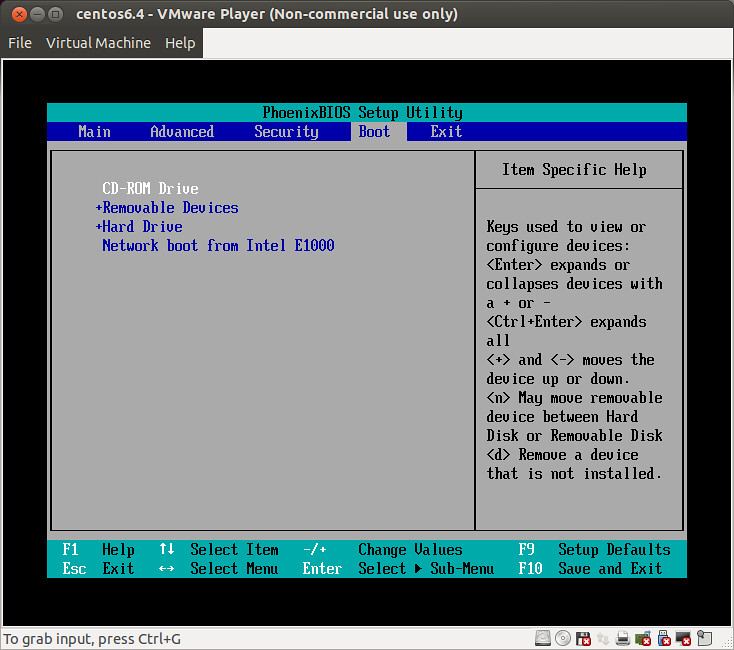
- BIOS will iterate though each device mentioned in the device boot order.
- How do BIOS know if a device is bootable?
- It checks bytes at position
511and512is0xAA55of the first sector. If yes then it’s a bootable device.
 Credit: https://www.flickr.com/photos/liewcf/3968289500/in/photostream/
When a bootable device is found
When BIOS found a bootable device then it would copy data from first sector of the bootable device to RAM starting from physical address 0x7c00.
The size of the sector can vary for a different device. For example
| Device | Sector Size |
|---|---|
| Floppy Disk | 512 Bytes |
| CD and DVD | 2 KB |
| Older HDD | 512 Bytes |
| Newer HDD | 4 KB |
As you have noticed that BIOS only loads the first sector into RAM and even with modern hardware you can’t get an actual OS in a single sector. For reference, Linux Kernel with basically everything stripped away will be in some MBs if not GB [ref]
So this is clear that BIOS could not load our OS for us. We would need to write a loader program which loads the kernel into RAM for us. Also, we need to make sure that our loader program fits into the first sector.
Since the smallest sector size is 512 Bytes we will write our loader within 512 bytes.
This program is called bootloader.
Bootloader
We will write our bootloader in the assembly language because this is the closed we can get to low-level language.
Let’s start with the minimum assembly that you would need to start. You can call it the boilerplate code.
bits 16

cli
hlt

times 510 - ($-$$) db 0
dw 0xAA55
Let me explain what each line means one by one.
bits 16
Every computer has 3 modes in which it can work.
- 16 Bit (Also called as Real Mode) learn more
- 32 Bit (Also called Protected Mode) learn more
- 64 Bit
To keep things simple just think that each mode defines the size of the register you can use.
When the computer starts it’s in 16 bit mode.
You can switch to different modes by doing some specific set of actions. Will come to this, later on.
This line explicitly tells the assembler that we want to produce the code designed to run on a 16-bit mode.
The good thing about this mode is that we have access to BIOS.
cli
This instruction stands for Clear all the interrupt. In 16 bit mode.
CPU is programmed to execute some block of code when an interrupt is triggered. An interrupt can be triggered by various sources like when press a keyboard button or timer is triggered.
For now, we are not concerned about any of this. We will just disable all of them.
hlt
It stands for Halt. You guessed it right.
It does stop any further code execution but it doesn’t mean you can’t run any code anymore. Interrupts can still be fired and CPU would execute the code. Unless you disabled the interrupts using cli.
One more myth you would come around is that it would put CPU in sleep mode or some low power mode. No, it doesn’t. Stackoverflow Answer
times 510 - ($-$$) db 0
This might look like the most complex line of all of them and to be honest, it is. But what it does is very simple and once we breakdown you would also see.
Remember when told that for the BIOS to identify if a device is bootable bytes at 511 and 512 should be 0xAA55.
The assembly code written above this line may or may not be of exactly 510 bytes. So we add some padding by adding zero to make it exactly 510 bytes.
$ is the address of the current line and $$ is the start of this section(In this case it would start of this file since we would be using flat binary).
So ($-$$) returns the size of the program before this line. Subtracting it from 510 - ($-$$) we get the number of bytes left to make it a 510 bytes file.
dw 0xAA55
By now you must have guessed it. It writes the boot signature after the 510 bytes.
dw stands for double word. Where a word means
Compiling and running the bootloader
For converting assembly language to machine code we would need an assembler.
There are many assemblers out there but we are going to use nasm for this. Because that’s what I know.
The second thing that you should know is the output file format. We would be using the binary file. This file is not divided into the section or any other complex logic as in ELF format.
First of all, create a new file boot.asm and wite the below code in it.
$ cat boot.asm
bits 16

cli
hlt

times 510 - ($-$$) db 0
dw 0xAA55
Next, we compile the above code using nasm
$ ./dockercross nasm -fbin boot.asm -o boot
You can check the bootloader size. It should be exactly 512 bytes only.
$ ls -la boot
-rw-r--r--  1 kshitijburman  staff  512 Dec 25 01:14 boot
To run this bootloader we would be using qemu
$ qemu-system-i386 -fda boot
You should get a window like this
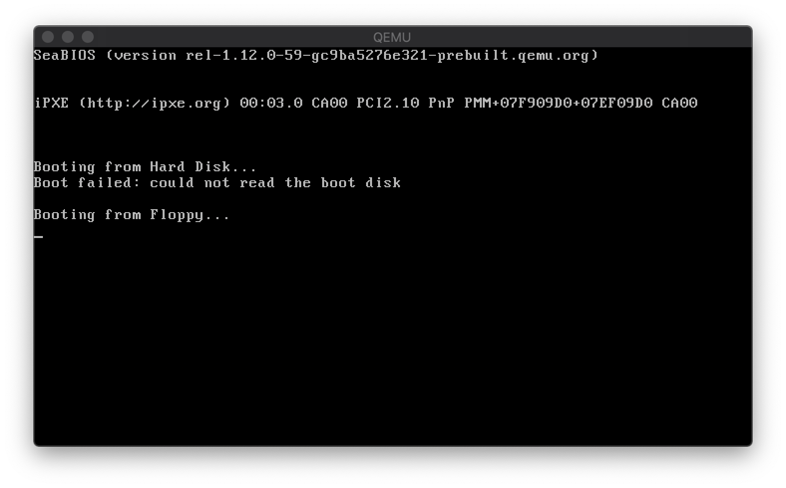
Congratulations!! You got your first bootloader up and running.
Will continue bootloader in the next post.